bldc motor controller design principles circuit examples.
3 22 2021 march 30 2021 19 min right of entry dc motor controller what it is design principles circuit examples supported by our own experience this article provides an initiation instigation to the control systems of dc motors.

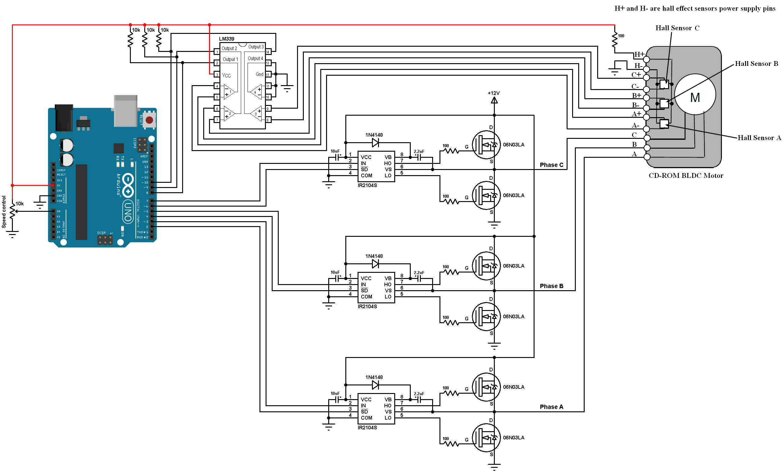
bldc motor control using arduino zeal control with.
12 4 2018 the 10k potentiometer is used to revise the readiness of the bldc motor its output is joined to arduino analog channel 0 a0 brushless dc motor control once arduino code.
motor starter control circuit diagram electrical a2z.
motor starter control circuit diagram in this guide you will learn virtually how control circuit diagrams are created for motor starters.
sensorless bldc motor controller using pic18f4550 microcontroller.
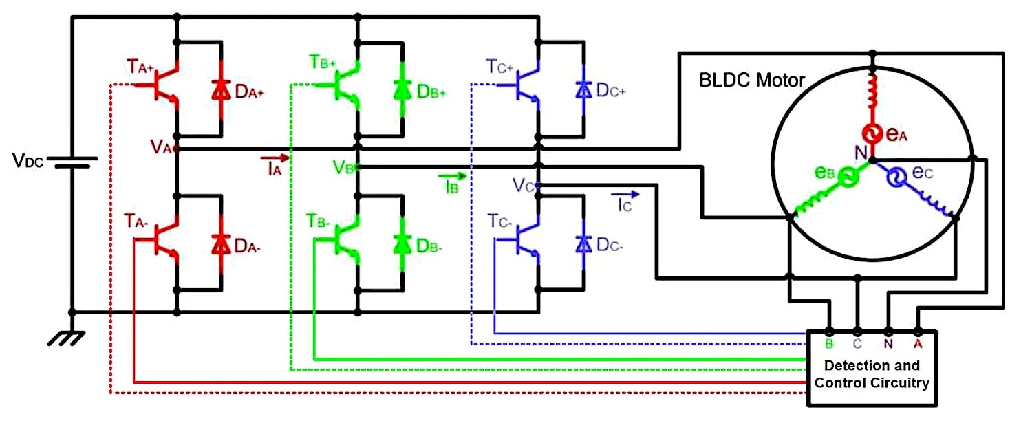
3 9 2018 past pic18f4550 8 bit microcontroller we can easily produce develop a user-friendly esc electronic eagerness controller for brushless dc motors this topic shows how did i made an esc using the pic18f4550 and few bonus components the sensorless bldc motor control technique is based regarding the bemf produced in the stator windings.
sensorless bldc motor control next arduino diy esc simple.
1 8 2018 this topic shows how to produce develop a sensorless brushless dc bldc motor controller or helpfully an esc electronic promptness swiftness controller using arduino there are two types of brushless dc motors sensored and sensorless sensorless bldc motor commutation is based just about the bemf produced in the stator windings.

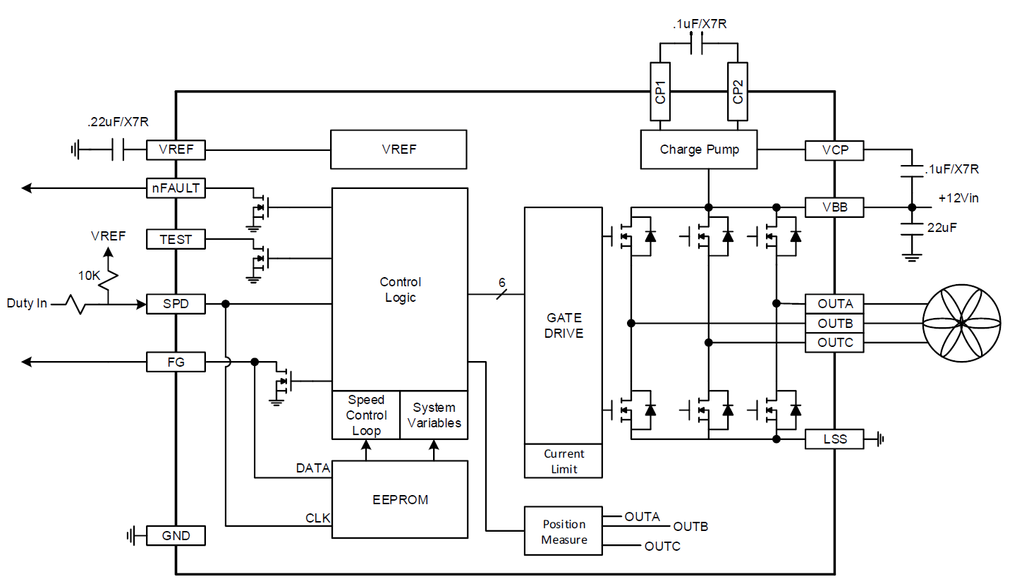
lv88551 motor driver single phase pwm full wave bldc motor.
lv88551 lv88552 lv88553 lv88554 www onsemi com 2 block diagram tsd lock detection osc purpose determination control logic 5v regulator a d converter level shift current.
50v 3 phase bldc motor driver homemade circuit projects.
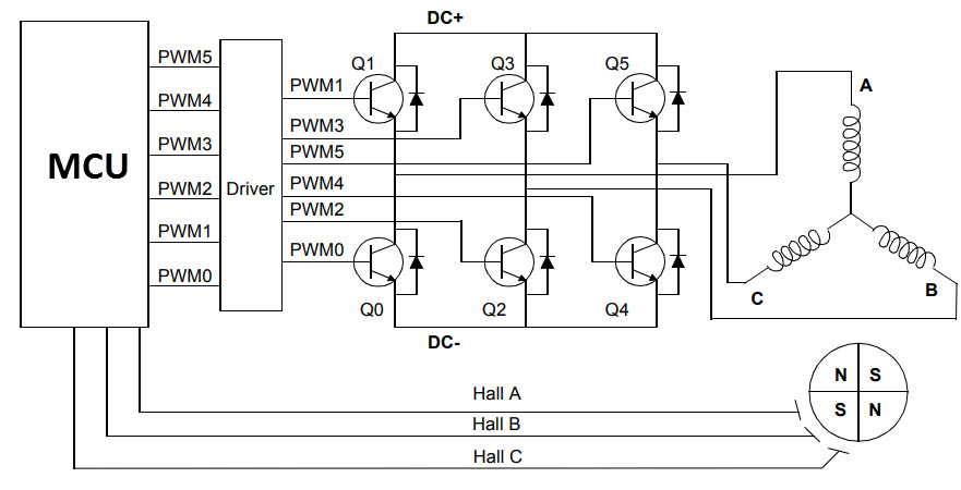
3 3 2021 chip internal structure the chips integrates all the circuitry required for effectively driving a 3 phase bldc motor as explained below a 3 phase dmos bridge a constant off era pwm current controller and the decoding logic for single the end hall sensors for generating the essential 120 degree phase shift sequence for the facility stage.
bldc motor controller in the same way as 16bit cpu pdf exonerate download.
1 adance product nformaton feb 19 2015 features approach door aspiration circuit for b6 nmo bridge c supply voltage range 7to 28 extended 5 to 42 cpu 16 bit 4 48mhz for application tasks 32 kbyte flah ecc protected 4 kbyte ram parity protected typical deep sleep mode current 20ua 2nd window watchdog independent clock and silicon ln2 x ln1 3 or bidirectional pwm nterface flashable via ln ud.
how to build a high torque dc motor speed controller circuit.
9 11 2010 are you fed up similar to dull pwm circuits which get not provide perfect dc motor eagerness control especially at lower speeds then check out this outstanding single chip pwm motor speed controller circuit that will find the money for you a given 360 degrees of for all time varying motor readiness control right from zero to maximum the zeal is controlled through an externally applied changing shifting dc voltage source.